|
|
|
|
|
Distinctive peculiarities of the devices «BIOMEDIS M» and «BIOMEDIS»
|
The distinctive feature of the devices of this series in comparison with analogues is following: the method of direct digital synthesis (DDS) of frequency is used for generation of treating signals; it allows getting high accuracy of frequency setting.
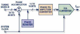 The functional scheme of the synthesizer DDS is showed on the picture 1: its main components include a stacker for value of a phase (phase accumulator), a tool for converting phase value into amplitude (it is usually a memory device, containing table with function sine values) and the Digital-to-Analogue Converter (DAC). The functional scheme of the synthesizer DDS is showed on the picture 1: its main components include a stacker for value of a phase (phase accumulator), a tool for converting phase value into amplitude (it is usually a memory device, containing table with function sine values) and the Digital-to-Analogue Converter (DAC).
The scheme DDS generates sinusoidal signal, having given frequency. The output frequency is determined by two parameters: the clock signal and the binary number written in frequency register. The binary number written in the frequency register is available at the input of the phase accumulator. If the memory device, containing tabular function sine values, is used, the phase accumulator defines the address (which corresponds to instant phase value) and sends it to the input of the memory device; thus we get the current value of amplitude in digital form at the output of the memory device. Then the DAC converts the digital value into the corresponding value of voltage or current. For generating sine wave with fixed frequency a constant value (increment of phase which is determined by the binary number written in frequency register) is added to the value saved in phase accumulator with every impulse of clock signal. If value of increment is great, the phase accumulator will quickly run the table of sinuses contained in the memory device, and signal of frequency will be high. If the value of increment is low, the phase accumulator will need more steps in order to run the whole table of the memory device, and that's why the signal of frequency will be low at the output.
The Digital-to-Analogue Converter (DAC) made on the same crystal with the generation's scheme of digital counts (DDS) represents the complete integral DDS synthesizer.
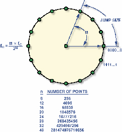 Instant phase value of continuing sinusoidal signal changes cyclically within the diapason, ranging from 0 to 2?. The phase's value generates in digital form. The transfer's function which is contained in the counter allows realizing the continuing cyclic change of phase's value in the synthesizer DDS. Imagine sinusoidal oscillations in the form of vectors rotating around the wheel (picture 2) in order to understand how generation takes place! Each point on the wheel corresponds to certain point of sine wave. While vector rotates around the wheel, the value of the sine of angle is an output signal. One turnover of the vector, having constant speed, provides generation of a sine wave's period. Instant phase value of continuing sinusoidal signal changes cyclically within the diapason, ranging from 0 to 2?. The phase's value generates in digital form. The transfer's function which is contained in the counter allows realizing the continuing cyclic change of phase's value in the synthesizer DDS. Imagine sinusoidal oscillations in the form of vectors rotating around the wheel (picture 2) in order to understand how generation takes place! Each point on the wheel corresponds to certain point of sine wave. While vector rotates around the wheel, the value of the sine of angle is an output signal. One turnover of the vector, having constant speed, provides generation of a sine wave's period.
The phase accumulator generates angle's values, having equal increments; the value contained in the phase accumulator corresponds to certain point of the circle.
The phase accumulator represents a modulo-M counter; the value of the counter increases each time it gets a clock impulse. The value of increment is specified by the binary number M. This number determines the value of phase's increment with each clock impulse; this number actually determines the quantity of counts skipped while rotating around the wheel. The greater the step is, the more quickly the phase accumulator overflows and the shorter the period of sine wave is. Total number of possible phase values is determined by phase accumulator's resolution; and then the total number of possible phase's values determines frequency resolution of the synthesizer DDS (n). The accumulator will overflow after 228 cycles (clock impulses) for 28-bit phase accumulator, if the value M = 0000…0001. The accumulator will overflow after 2 cycles (the minimum of cycles which meet required criteria by Nyquist), if the value M = 0111…1111. This relationship is described by the following simple formula:
fout = М x fc/2^n
where:
fout is frequency of output signal of DDS;
М is the binary number which determines frequency of signal;
fc is frequency of clock signal;
n is length of the phase accumulator.
If the value M is changed, the frequency is immediately changed at the output of the synthesizer; the signal doesn't have any interruption in this case. Loop settling time doesn't take place here, as it is incurred in the case of phase-locked loop. The number of counts per once cycle decreases in case of increasing output frequency. Since the theory of counts requires at least two counts per cycle for complete reconstruction of output signal, the maximum frequency of the DDS synthesized signal is fc/2. But the practice shows that the frequency of synthesized signal is actually limited by lower value; this condition provides improvement of the synthesized signal's quality and easing of its filtering. When the signal of constant frequency is generated, the code at the output of the phase accumulator increases linearly; it corresponds to linear analog ramp signal.
The memory device, containing tabular values of sinus, is used for converting of phase accumulator's output code into instant amplitude values. Insignificant bits of 28-bit code are eliminated; we get a 10-bit code at the output of tabular memory device; the code is sent to DAC. Since the sine wave has symmetrical nature, the DDS synthesizer saves only the data of one-quarter-cycle of the sine wave. The tabular memory devices generates the complete cycle of the sine wave by reading data forward and then back.
DDS AD9832 with 32-bit phase accumulator is used in the devices "BIOMEDIS M" and "BIOMEDIS; it allows setting frequency with the following accuracy: 8 MHz / 2^32= 0,00186264514923095703125 Hz within the diapason of frequencies ranging from 0 to 4000000 Hz.
Now let examine the principle of generating treating signals by similar devices that don't use DDS. The elaborators have utilized a simple way: the way of dividing the signal of clock cycle into integer number, while using inserted timers of processor or through organizing of program divider.
For example, we want to generate a signal, having certain frequency F-output or cycle T-output through microprocessor. We can divide the clock frequency Fclock only into certain integer number n and get Foutput /n at the output.
Let see what we get in this case. If the frequency of clock generator is 5 MH:
| N | F-output |
| 643 | 7776,05 |
| 644 | 7763,975 |
| 645 | 7751,938 |
| 646 | 7739,938 |
| 647 | 7727,975 |
| 648 | 7716,049 |
| 649 | 7704,16 |
| 650 | 7692,308 |
| 651 | 7680,492 |
| 652 | 7668,712 |
| 653 | 7656,968 |
| 654 | 7645,26 |
| 655 | 7633,588 |
| 656 | 7621,951 |
| 657 | 7610,35 |
| 658 | 7598,784 |
| 659 | 7587,253 |
| 660 | 7575,758 |
| 661 | 7564,297 |
| 662 | 7552,87 |
| 663 | 7541,478 |
| 664 | 7530,12 |
| 665 | 7518,797 |
| 666 | 7507,508 |
| 667 | 7496,252 |
| 668 | 7485,03 |
| 669 | 7473,842 |
| 670 | 7462,687 |
| 671 | 7451,565 |
| 672 | 7440,476 |
| 673 | 7429,421 |
| 674 | 7418,398 |
| 675 | 7407,407 |
| 676 | 7396,45 |
| 677 | 7385,524 |
| 678 | 7374,631 |
| 679 | 7363,77 |
| 680 | 7352,941 |
| 681 | 7342,144 |
| 682 | 7331,378 |
| 683 | 7320,644 |
| 684 | 7309,942 |
| 685 | 7299,27 |
| 686 | 7288,63 |
For example, we need the frequency = 7334 Hz (it is the second frequency by Rife in case of Chemtrail detox). As it is seen in the table above, the frequency is not included in the table. The nearest frequencies are following: 7342,144 and 7352,941 Hz. Or for example, we need to get the frequencies 7848 and 7847 Hz (the first frequencies of E-coli). The frequencies are greater; it means that the step is larger. So, we fail again.
The step of the greed approaches 0,1 Hz in case of output frequencies which are equal to about 720 Hz.
| N | F-output |
| 4143 | 1206,855 |
| 4144 | 1206,564 |
| 4145 | 1206,273 |
| 4146 | 1205,982 |
The step of the greed approaches 0,1 Hz in case of output frequencies which are equal to about 720 Hz.
| N | F-output |
| 6921 | 722,439 |
| 6922 | 722,3346 |
| 6923 | 722,2302 |
| 6924 | 722,1259 |
| 6925 | 722,0217 |
| 6926 | 721,9174 |
| 6927 | 721,8132 |
| 6928 | 721,709 |
| 6929 | 721,6048 |
| 6930 | 721,5007 |
| 6931 | 721,3966 |
| 6932 | 721,2926 |
| 6933 | 721,1885 |
| 6934 | 721,0845 |
| 6935 | 720,9805 |
| 6936 | 720,8766 |
| 6937 | 720,7727 |
| 6938 | 720,6688 |
| 6939 | 720,5649 |
| 6940 | 720,4611 |
| 6941 | 720,3573 |
| 6942 | 720,2535 |
| 6943 | 720,1498 |
| 6944 | 720,0461 |
| 6945 | 719,9424 |
| 6946 | 719,8388 |
| 6947 | 719,7351 |
It means that the lower the frequency of generating signal is, the narrower the step of the greed is. The accuracy of 0.01 Hz is provided only in the diapason ranging till 100 Hz.
The next distinctive peculiarity of the devices "BIOMEDIS M" and "BIOMEDIS" is usage of voltage increase converter. Why is it important?
The supply voltage of the whole device should be within of certain limits for stable work of the microprocessor and graphic indicator. The voltage needed for processor should usually range from 2.7 to 5.5 volts; the voltage range for indicator should be even narrower. Thus, if two AA batteries are used for supply, the voltage range for each of them is lower than 2.7 volts. As a result, the device fails to work (or it works improperly: the processor works but the indicator doesn't reflect data; intensity of radiation falls because it is in quadratic dependence on supply voltage). The absence of the voltage increase converter doesn't allow replacing the batteries AA by rechargeable accumulators that provide saving money in case of prolonged usage of the device. The devices "BIOMEDIS M" and "BIOMEDIS" contain voltage increase converters, having the efficiency coefficient of 98% that allows supporting the voltage on the supply line of the device at the level of 5V in case of input diapason ranging from 0,8 to 6 V. The working time of the device increases till replacing of supply elements in this case; moreover, the user can be sure that stability of radiation's intensity is provided.
|
|
|
|
|
|
|